Notes on D.4 Induction
Electromagnetic induction is the production of an emf, and so a current, by a changing magnetic field. It is the reverse of the motor effect: instead of a current in a field producing motion, motion in a field (or a field that changes) produces a current. Most of the world’s electricity is generated this way, by coils turning in magnetic fields in power stations driven by steam, water or wind.
Michael Faraday discovered the effect in 1831, after years of searching for a way to turn magnetism into electricity. Within a few decades induction had made large-scale electricity generation possible, and with it electric lighting, electric motors in factories and electric railways. The same physics now works in electric guitar pickups, induction hobs, wireless phone chargers and the regenerative brakes of electric cars.
Magnetic flux and flux linkage
Whether an emf is induced depends on how much magnetic field passes through a circuit, and on how this quantity changes. That quantity is the magnetic flux. For a flat area in a uniform magnetic field of flux density , the flux through the area is
where is the angle between the field and the normal to the area (the line at right angles to its surface). When the field passes straight through the area, and the flux is a maximum, . When the field runs parallel to the surface,
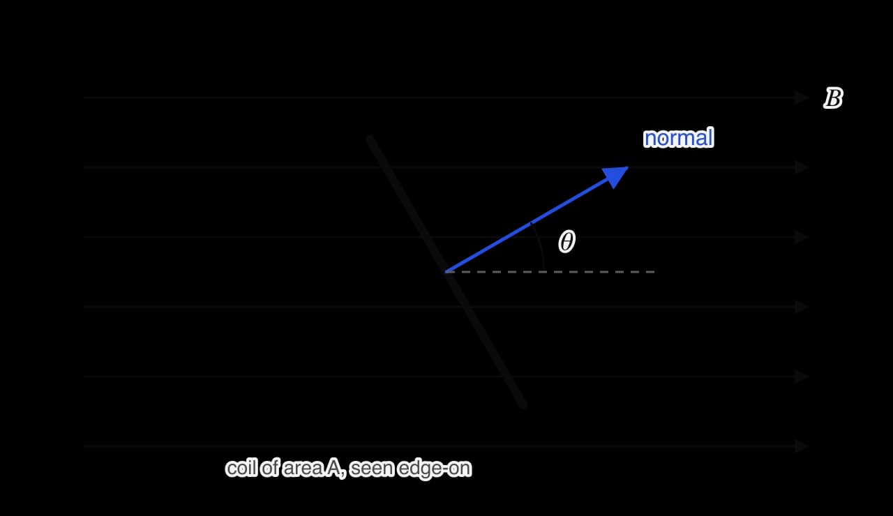
One way to picture magnetic flux is as the number of field lines passing through the area. In this picture the magnetic flux density is the number of lines per unit area, which is where its name comes from. The weber is a large unit: the flux through a loop held flat in the Earth’s field is only about
Flux linkage
A coil of turns has the same flux through each turn, and the emf induced in each turn adds up in series. The useful quantity for a coil is therefore the flux linkage:
Flux linkage is also measured in webers (sometimes written "Wb turns"). A coil with 500 turns in a given field has 500 times the flux linkage of a single loop of the same area, and 500 times the emf when the flux changes.
Inducing an emf
The simplest induction experiment uses a bar magnet, a coil and a galvanometer, a sensitive ammeter with its zero in the centre of the scale. Pushing the magnet into the coil makes the pointer flick one way; pulling it out makes the pointer flick the other way. Holding the magnet still, even deep inside the coil, gives no reading.
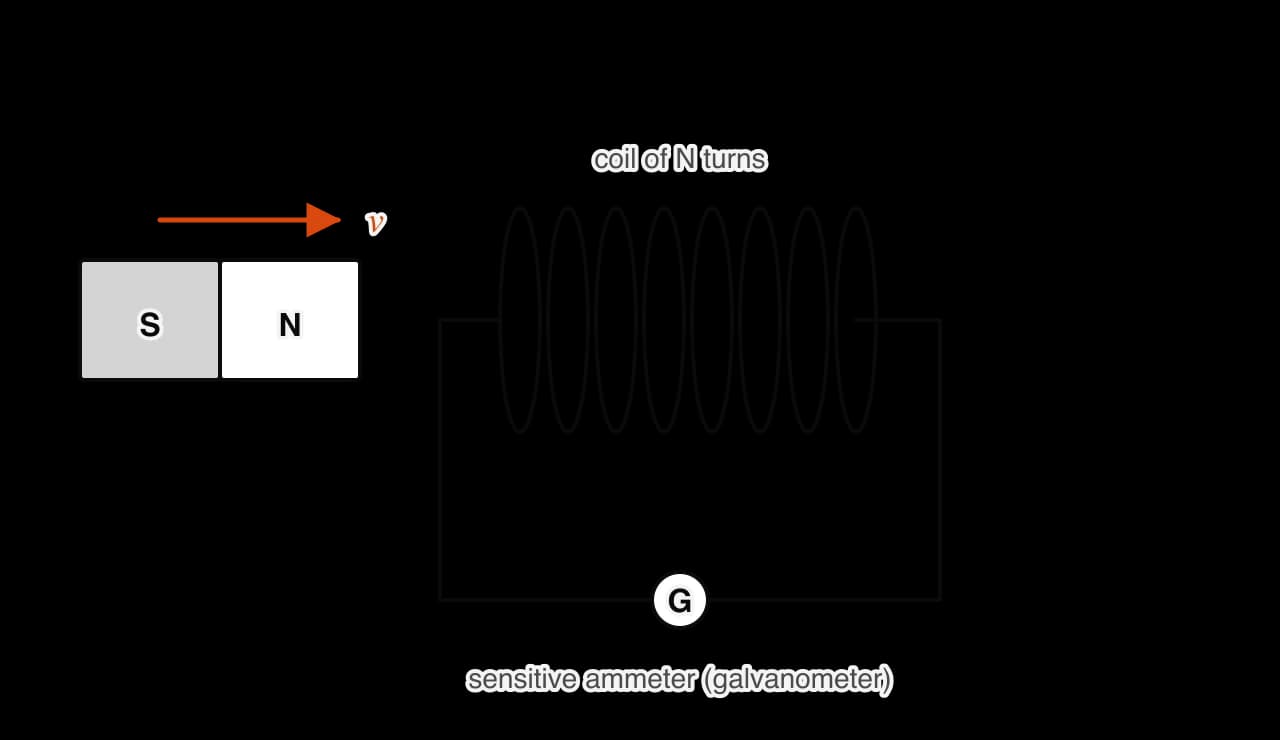
Repeating the experiment in different ways establishes a set of observations:
A current flows only while the magnet and the coil are moving relative to each other. Moving the coil towards a stationary magnet has the same effect as moving the magnet.
Reversing the direction of motion, or turning the magnet round, reverses the current.
Moving the magnet faster gives a larger current that lasts a shorter time.
A stronger magnet, or a coil with more turns, gives a larger current.
Faraday saw that all these observations have one cause: the flux linking the coil is changing. An emf is induced whenever the flux linkage of a circuit changes, by any means. Since , the flux linkage can change in three ways:
What changes | Example |
|---|---|
The flux density | A magnet moved towards or away from a coil; the current in a nearby electromagnet switched on, off or varied |
The area inside the field | A coil moved into or out of a field region; a rod sliding along rails, enclosing more area |
The angle | A coil rotating in a uniform field, as in a generator |
An emf is induced whether or not the circuit is complete. If it is complete, the emf drives an induced current through the circuit’s total resistance . If the circuit is broken, a potential difference appears across the gap but no current flows.
Faraday’s law
The size of the induced emf depends on how quickly the flux linkage changes. Faraday’s law states this precisely.
The minus sign expresses Lenz’s law, which gives the direction of the emf. When only the size of the emf is wanted, the magnitude is used. If the flux changes at a steady rate, the emf is constant; if the rate varies, the equation gives the average emf over the interval .
Faraday’s law explains each observation of the magnet-and-coil experiment. A faster movement changes the flux in a shorter time, so the emf is larger. More turns multiply the flux linkage. A stationary magnet produces no change in flux, so no emf. The law also shows that a weber is the same as a volt second: an emf of 1 V is induced when the flux linkage changes at 1 Wb every second.
 YouTube
Emf from a flux-linkage graph
Faraday’s law says the emf is minus the rate of change of flux linkage, and a rate of change is a gradient. On a graph of flux linkage against time, the emf at any moment is minus the gradient of the graph at that moment. Where the graph is flat, the emf is zero; where it is steepest, the emf is largest. In the reverse direction, the area under an emf–time graph equals the total change in flux linkage.
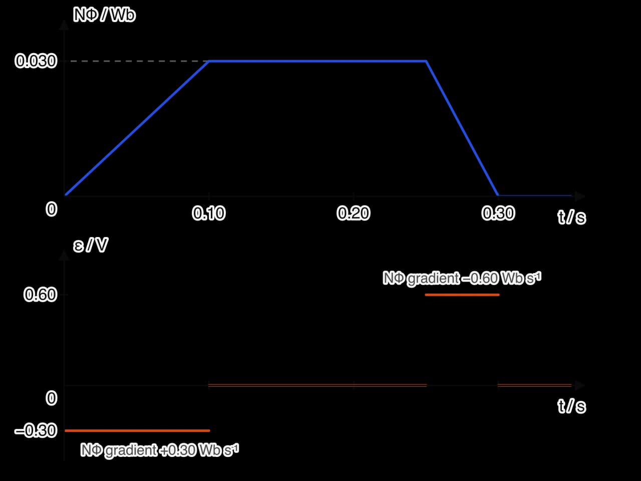
In the pair of graphs, the flux linkage rises by 0.030 Wb in 0.10 s, a gradient of , so the emf is V. Between 0.10 s and 0.25 s the flux linkage is constant and there is no emf. It then falls by 0.030 Wb in 0.05 s, a gradient of , so the emf is
The emf induced in a moving conductor
A straight conductor moving through a magnetic field has an emf between its ends, even when it is not part of a complete circuit. Two explanations lead to the same result: one from the force on the charges in the conductor and one from Faraday’s law.
Explanation from the magnetic force on charges
A metal rod of length moves at speed at right angles to a uniform field , with the rod also perpendicular to the field. The free electrons in the rod move with it, so each feels a magnetic force along the rod. The electrons drift to one end, which becomes negative, leaving the other end positive.

The separated charges produce an electric field along the rod, which pushes the electrons back. The drift stops when the electric force balances the magnetic force, , so . The potential difference between the ends of a rod of length in a uniform field
Explanation from Faraday’s law
In a time the rod moves a distance and sweeps out an area . The flux through this area is the flux the rod has "cut",
The two explanations agree, which is a useful check that Faraday’s law describes the same physics as the magnetic force on moving charges. The flux-cutting picture is often the quickest way to find the emf in a moving conductor.
Lenz’s law and the direction of the induced current
Faraday’s law gives the size of the induced emf. Its direction follows from a separate principle, Lenz’s law.
When a N pole is pushed towards a coil, the flux through the coil increases. The induced current flows in the direction that makes the near face of the coil a N pole too, so the coil repels the approaching magnet. When the magnet is pulled away, the induced current reverses, the near face becomes a S pole, and the coil attracts the magnet, opposing its departure. In both cases the force on the magnet opposes its motion relative to the coil.
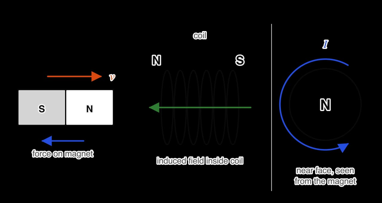
The direction of a current in a coil and the pole it produces are linked by the right-hand grip rule: curl the fingers of the right hand along the current, and the thumb points out of the N face. Equivalently, a face round which the current flows anticlockwise, seen from outside, is a N pole.
Lenz’s law and the conservation of energy
Lenz’s law is a consequence of the conservation of energy. Suppose the induced current had the opposite direction, so that the approaching N pole were attracted into the coil. The magnet would then speed up without anything pushing it, the current would grow, the attraction would grow, and kinetic and electrical energy would appear from nothing, which would break the conservation of energy.
Because the induced current opposes the motion, work must be done to move the magnet against the opposing force. That work is the source of the electrical energy, which ends up as internal energy in the resistance of the circuit. This is why a generator becomes harder to turn when a load is connected and current flows.
A magnet falling through a coil
A bar magnet dropped through a vertical coil connected to a data logger produces two pulses of emf. As the magnet enters, the flux linkage increases and the emf has one sign. When the magnet is half-way through, the flux linkage is at its maximum and momentarily constant, so the emf is zero. As the magnet leaves, the flux linkage decreases and the emf has the opposite sign.
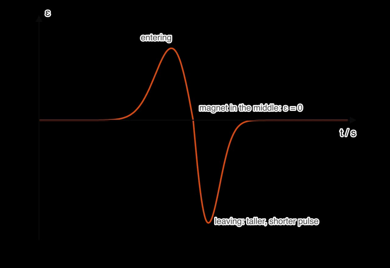
The magnet accelerates as it falls, so it leaves the coil faster than it entered. The second pulse is therefore taller (a faster change of flux) and narrower (a shorter time). The area under each pulse is the change in flux linkage, the same in both, so the two areas are equal. If the coil is part of a complete circuit, the induced current exerts an upward force on the magnet each time, by Lenz’s law, and the magnet falls with slightly less acceleration than .
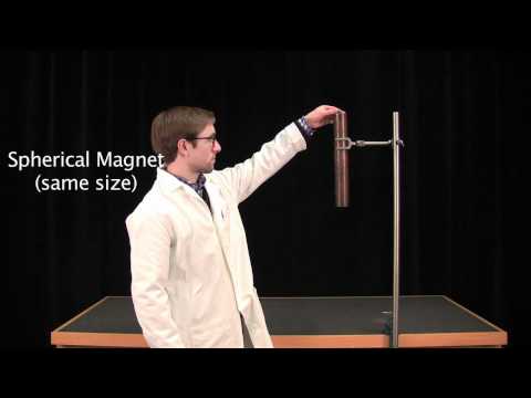
The effect is much larger with a strong magnet and a thick metal tube. A neodymium magnet dropped down a vertical copper pipe falls slowly, taking seconds to emerge, while a non-magnetic object of the same size falls straight through. Currents induced in the walls of the pipe oppose the motion of the magnet, and the magnet quickly reaches a low terminal speed.
A magnet oscillating on a spring
A magnet hanging from a spring above (or partly inside) a coil produces an alternating emf as it bounces. As the magnet moves towards the coil the flux linkage increases, and as it moves away the flux linkage decreases, so the emf changes sign twice in each oscillation. The emf is largest near the equilibrium position, where the magnet moves fastest, and zero at the top and bottom of each oscillation, where it is momentarily at rest. If the coil is connected to a resistor, the induced current opposes the motion each way, and the oscillations die away faster than they would with the circuit open: kinetic energy of the magnet is transferred to internal energy in the resistor.
A geophone, used by seismologists and in oil and gas surveys, works on this principle. A magnet and a coil are mounted so that one of them is held by a spring and stays almost still while the case moves with the ground. Vibrations of the ground then make the coil and magnet move relative to each other, and the induced emf is proportional to the rate at which the flux linkage changes, and so to the speed of the ground. More turns on the coil or a stronger magnet give a larger emf for the same vibration, making the instrument more sensitive.
 YouTube
Eddy currents
The currents in the copper pipe are an example of eddy currents: loops of induced current that flow inside a solid piece of metal when the flux through it changes. By Lenz’s law they always oppose the change, and they dissipate energy in the metal as internal energy. They are used in magnetic brakes on trains and roller coasters, which slow a moving metal fin passing between magnets without any contact or wear.
An induction hob uses eddy currents to heat food. An alternating current at a frequency of tens of kilohertz in a coil beneath the glass surface produces a rapidly changing magnetic field. This field induces eddy currents in the base of an iron or steel pan, which heat the pan directly while the glass stays relatively cool. A pan made of glass or ceramic does not heat at all, because there is no conductor for the currents to flow in. A wireless phone charger also uses a changing field from a coil in the pad, but here the induced emf drives a current in a second coil inside the phone, which charges its battery.
Self-induction
A coil carrying a current is linked by its own magnetic flux. If the current in the coil changes, this flux changes, and an emf is induced in the coil itself. This is self-induction. By Lenz’s law the induced emf opposes the change in current, so it is often called a back emf: it slows the rise of current when a circuit is switched on and tries to keep the current flowing when it is switched off.
Self-induction has visible effects in circuits with large coils. When the current through an electromagnet is suddenly switched off, the flux collapses very quickly and the back emf can be large enough to make a spark jump across the switch contacts. A lamp in series with a large coil lights a moment later than an identical lamp in series with a resistor, because the back emf delays the growth of the current.
A rod on rails: forces and energy
A metal rod sliding along two parallel conducting rails, joined at one end by a resistor, makes a complete circuit whose area grows as the rod moves. This arrangement shows the emf, the current, the opposing force and the energy transfers of induction all together.
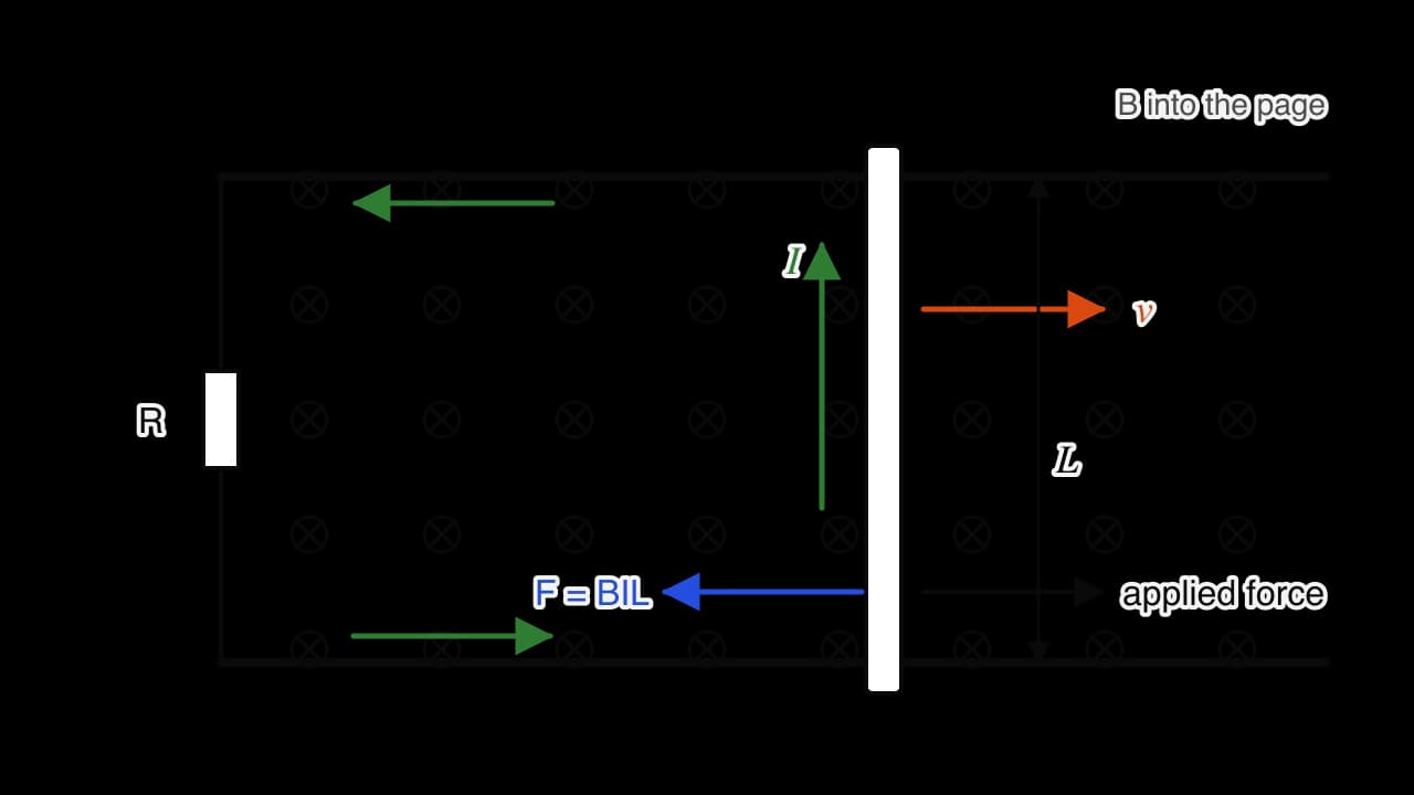
A rod of length between the rails, moving at speed in a field , has an emf . With a total circuit resistance , the current is
The current in the rod is in a magnetic field, so the rod feels a force . By Lenz’s law this force opposes the motion. Substituting for gives
The retarding force is proportional to the speed. To keep the rod moving at constant speed, an applied force of the same size must push it forwards. The mechanical power supplied is , and the electrical power dissipated in the resistance is :
The two powers are equal. Every joule of work done by the applied force becomes a joule of electrical energy, which is dissipated as internal energy in the resistor. This equality is the quantitative form of the energy argument for Lenz’s law.
Terminal speed
If a constant force acts on a rod that starts from rest, the rod accelerates, but the retarding force grows with its speed. The rod reaches a terminal speed when the retarding force equals the applied force:
The same reasoning applies to a rod falling down vertical rails in a horizontal field, where the weight is the constant force. It is the same idea as a skydiver reaching terminal speed when fluid resistance balances their weight, and it explains the slow fall of a magnet through a copper pipe.
A coil moving into and out of a field
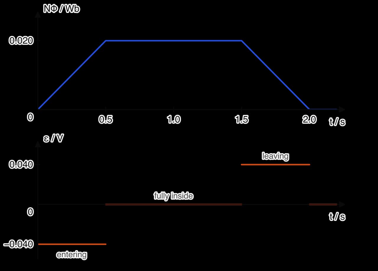
A rectangular coil pulled at constant speed through a region of uniform field has an emf only while its flux linkage is changing, which happens while one edge is inside the field and the opposite edge is outside.
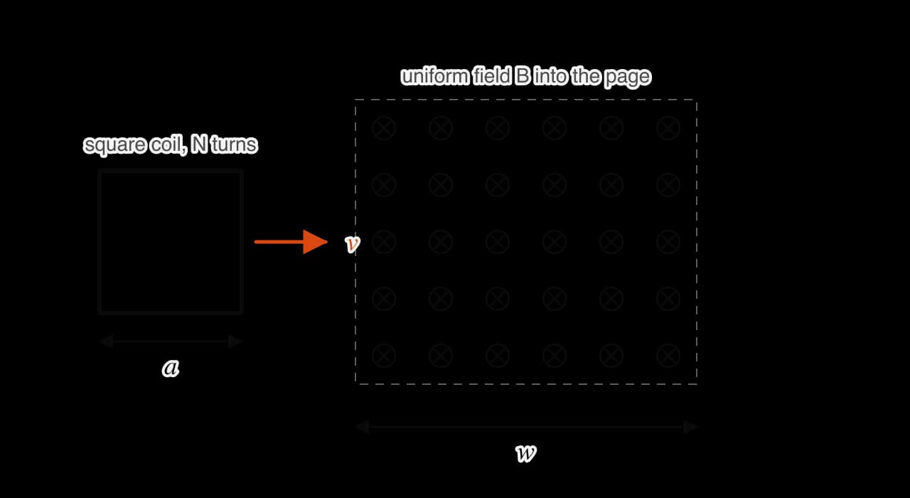
For a square coil of side and turns moving at speed into a field region wider than the coil, there are three stages:
Entering. The leading edge is inside the field and cuts flux, so the area of coil inside the field grows at a rate . The emf is , constant while the coil enters, which takes a time .
Fully inside. The flux linkage is constant at
If the coil is part of a closed circuit, an induced current flows while it enters and leaves, and by Lenz’s law the magnetic force on the coil opposes its motion at both stages. A force must be applied to pull the coil steadily into the field and again to pull it out.
A coil rotating in a uniform field
When a flat coil of turns and area rotates at constant angular speed about an axis at right angles to a uniform field, the angle between its normal and the field increases steadily: . Its flux linkage therefore varies as
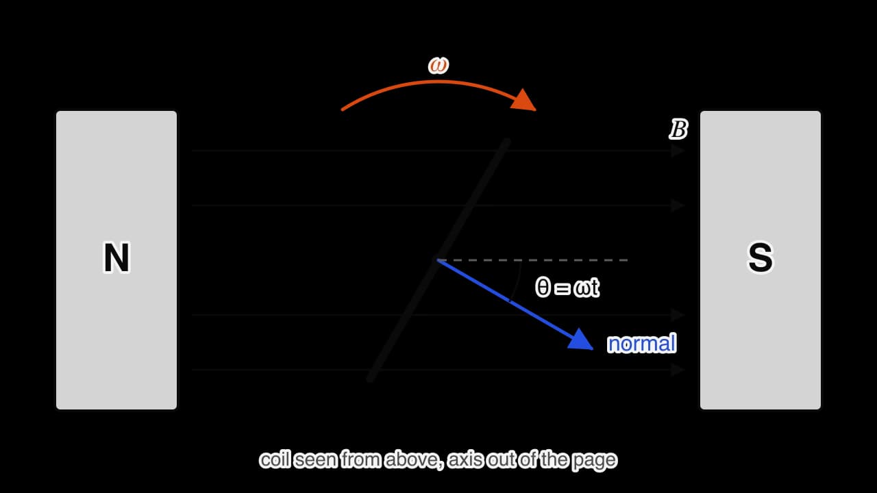
The flux linkage is a cosine function of time. The emf, which is minus its rate of change, is a sine function:
The emf alternates: it is positive for half of each rotation and negative for the other half, with the same frequency as the rotation, . This is an alternating emf, and the current it drives through a load is an alternating current.
The 90° phase difference between the two graphs follows from the gradient rule. The flux linkage is greatest when the plane of the coil is at right angles to the field, but at that instant the sides of the coil move parallel to the field lines, cut no flux, and the emf is zero. A quarter of a turn later, the plane of the coil is parallel to the field. The flux linkage is zero, but the sides of the coil are moving straight across the field lines, cutting flux as fast as possible, and the emf is at its peak.
Deriving the peak emf NBAω
Let the coil have two sides of length parallel to the axis, a distance apart, so . Each of these sides moves in a circle of radius at speed
Changing the rotation frequency
The rotation frequency affects the emf in two ways at once. A faster rotation makes the flux linkage change faster, so the peak emf is larger. It also makes each cycle shorter, so the emf alternates at a higher frequency. Doubling the rotation frequency therefore doubles the peak emf and halves the period of the emf.
Generators
An ac generator turns kinetic energy into electrical energy using a rotating coil. In a simple generator, a coil is turned between the poles of a magnet. Each end of the coil is connected to a slip ring on the axle, and a fixed carbon brush presses on each ring. As the coil turns, each brush stays in contact with the same end of the coil, so the alternating emf of the coil appears unchanged across the load.
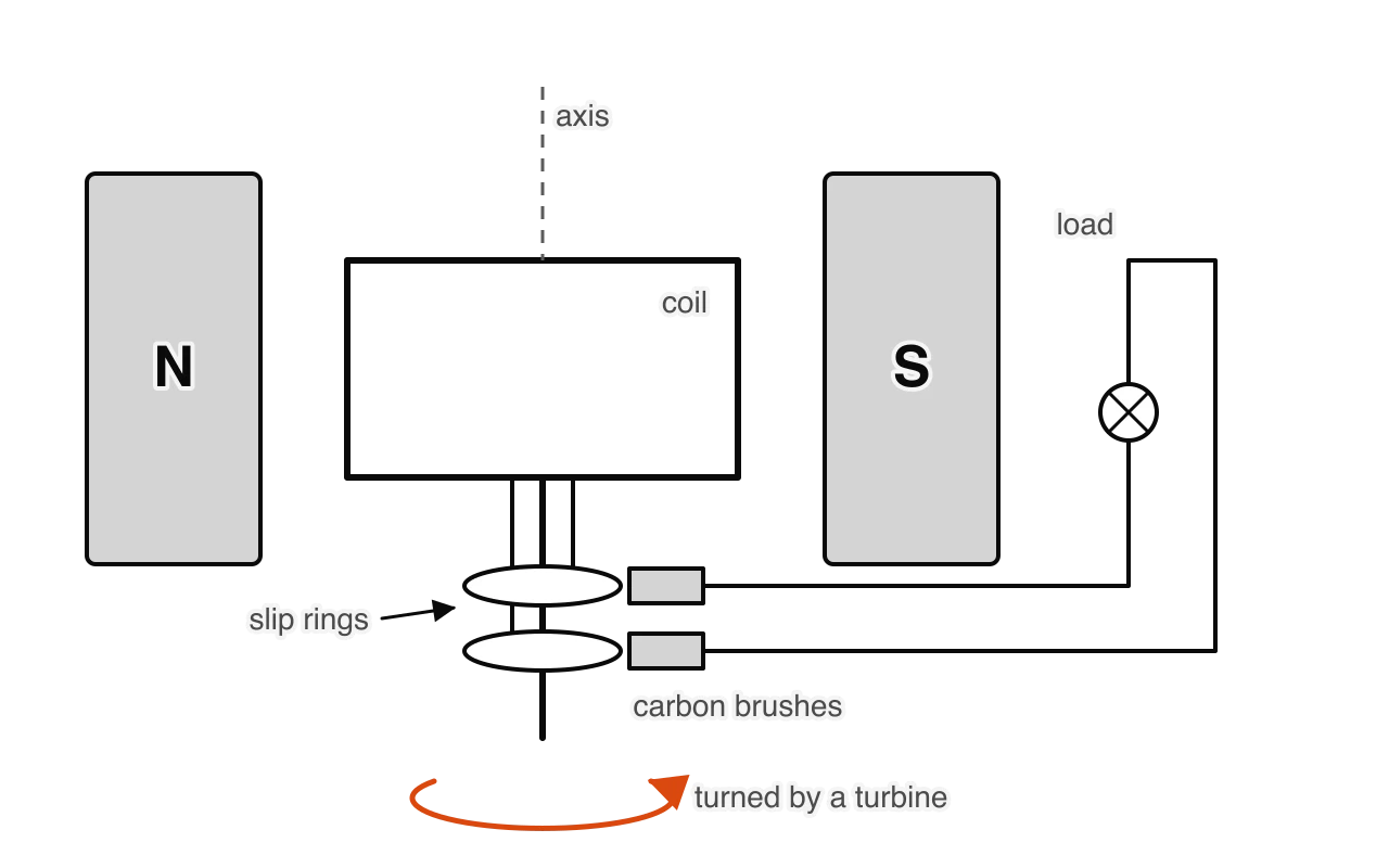
Since the peak emf is , the output of a generator can be increased in four ways:
using more turns of wire on the coil;
using a stronger magnetic field, for example electromagnets with iron cores;
using a coil of larger area;
turning the coil faster, which also raises the frequency of the output.
In a large power-station generator the arrangement is turned inside out: the field is produced by electromagnets on a rotating shaft (the rotor), and the emf is induced in heavy fixed coils around it (the stator). This avoids passing large currents through sliding contacts. The frequency of the output is fixed by the rotation rate. On a 50 Hz grid, such as those in Europe, a generator with a single pair of poles turns at 50 revolutions per second, 3000 revolutions per minute; on a 60 Hz grid it turns at 3600.
A generator that supplies current is harder to turn. When current flows, the current in its coils feels a magnetic force that opposes the rotation, by Lenz’s law. The turbine must do work against this force, and the harder the generator is worked, the more steam, water or wind is needed to keep it turning at the same speed. The regenerative brakes of electric and hybrid cars use the same effect deliberately: when the driver brakes, the drive motor is switched to work as a generator, the opposing force slows the car, and the electrical energy produced charges the battery instead of being lost as internal energy in the brakes.
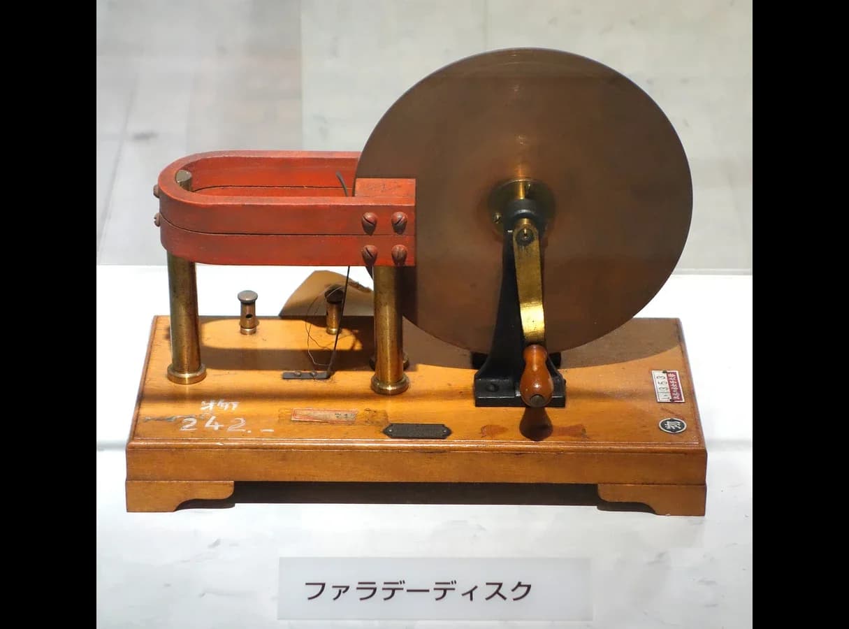
Faraday’s first generator, built in 1831, was a copper disc turned between the poles of a magnet. Each radius of the disc cuts flux as it turns, giving a steady emf between the axle and the rim. It produced only a small emf, but it showed that mechanical work could be converted continuously into electrical energy. About fifty years later, steam-driven generators were supplying electricity to the first public power stations, and electricity became the energy carrier of industrial societies.
Applying the ideas in exam questions
Paper 1A: flux through a tilted loop
Paper 1A: a generator turned twice as fast
Paper 1B: the peak emf of a small generator
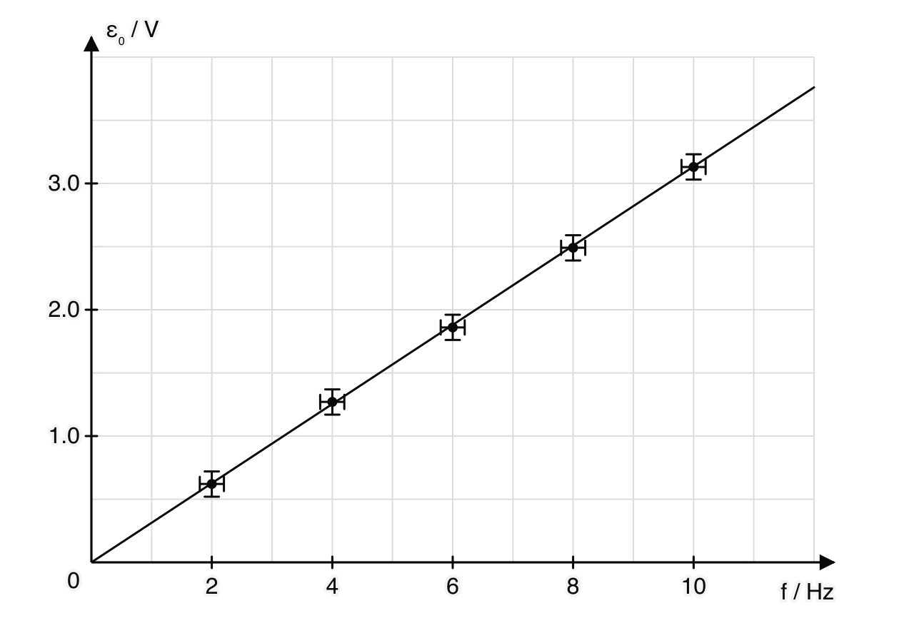
A group of students turn the coil of a small generator at different frequencies and measure the peak emf on a data logger. The coil has 250 turns and an area of
/ Hz | / V |
|---|---|
2.0 | 0.62 |
4.0 | 1.27 |
6.0 | 1.86 |
Paper 2: a rod falling on vertical rails
Paper 2: a coil pulled out of a field
Self-check
- To do:
I can define magnetic flux and flux linkage, use with the angle measured from the normal, and state the unit weber.
- To do:
I can describe experiments that induce an emf by changing the field, moving a conductor or magnet, or rotating a coil.
- To do:
I can state Faraday’s law and use to calculate an induced emf and current.
- To do:
I can find the emf from the gradient of a flux-linkage–time graph and sketch one graph from the other.